
10X Backbone: How Meta Is Scaling Backbone Connectivity for AI
- We’re sharing details on our journey to scale Meta’s Backbone network to support the increasing demands of new and existing AI workloads.
- We’ve developed new technologies and designs to address our 10x scaling needs and applying some of these same principles to help extend our AI clusters between multiple data centers.
Meta’s Backbone network is composed of a set of interconnected routing platforms and provides WAN (wide area network) connectivity among network locations. Meta has architected Backbone in two different networks: Classic Backbone (CBB) and Express Backbone (EBB). They differ in some fundamental ways.
CBB is used to achieve global reach from data centers (DCs) to our points of presence (POPs) where we connect with external carriers. CBB is flexible: It can shrink or grow to support a diverse set of geographies and accommodate a broad range of connectivity requirements. It uses traditional IP/MPLS-TE (Internet Protocol/Multiprotocol Label Switching/Traffic Engineering) technologies.
EBB, in contrast, is built to provide scalable DC-to-DC interconnection. EBB is less flexible, having a sizable minimum installation. It runs a heavily customised stack of software, such as the Open/R routing protocol, and an in-house traffic-engineering stack with onbox agents and a centralized controller.
While we see growth in both networks, it’s EBB that presents the most challenging scalability problems.
In the rest of this post, we will focus on EBB and describe how we actually addressed EBB’s growth and the resulting challenges.
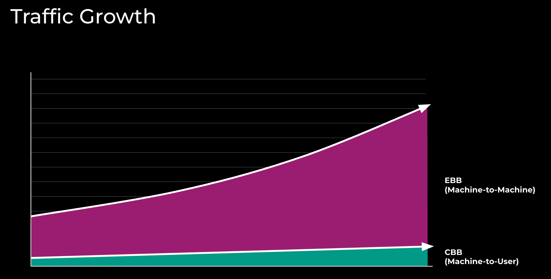 Figure 1: Traffic growth in Meta’s Backbone network
EBB network first started serving traffic around 2015. Figure 1 represents the growth since then for EBB, DC-to-DC traffic flows versus CBB, and DC-to-POP traffic flows.
Prior to 2015, CBB was used for both DC-to-DC and DC-to-POP traffic. Figure 2 represents some of the EBB adoption and technology milestones.
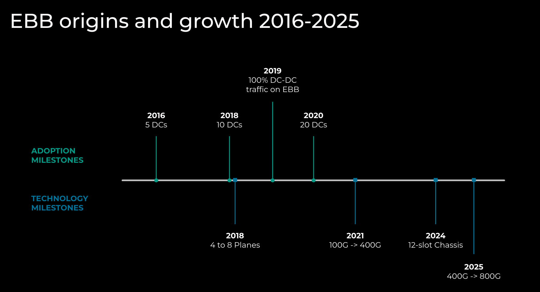 Figure 2: EBB origins and growth
A significant amount of fiber in terms of quantity and distance is required to interconnect DC locations at the necessary scale. The existing DCs continue to grow in footprint and capacity due to the addition of more powerful servers and, where possible, the addition of new buildings at existing locations.
Connecting DCs reliably and repeatedly at high capacity to the rest of the network can be challenging, especially due to the speed at which new DCs are being built. While the network has some input into the site-selection process, there are many influencing factors beyond ease of connectivity that determine how new data center locations are chosen.
10X Backbone
10X Backbone is the evolution of EBB in terms of scale, topology, and technology. Below are the three techniques used to scale to 10X Backbone.
DC Metro Architecture
Historically, building long-haul fibers to new DC locations has been painful, especially when these long-haul fibers need to extend hundreds of miles.
Our first technique to scale up to 10X Backbone was to pre-build some of the components of DC metro architecture. By pre-building them, we could more quickly provide connectivity to new DCs.
First, we built two rings of fiber to provide scalable capacity in the metro, and we connected long-haul fibers to the rings. Next, we built two POPs to provide connectivity toward remote sites. Last, we connected DCs to the rings, and therefore increased or enabled capacity between the DC and POPs. (See Figure 3.)
DC metro architecture has several advantages:
- A simplified building of DC connectivity and WAN topology
- A standardized scalable physical design
- Separate metro and long-haul networks
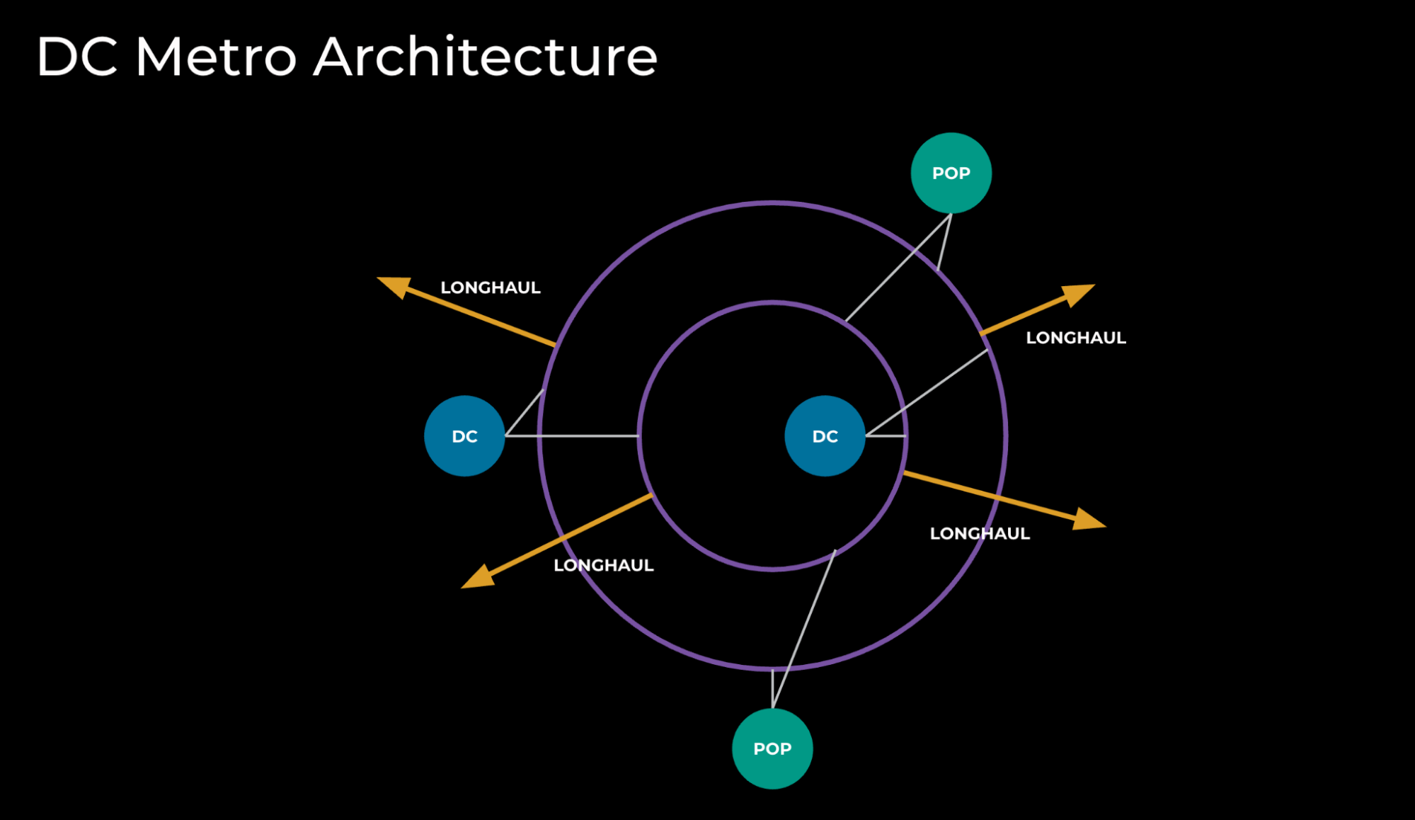 Figure 3: DC metro architecture
IP Platform Scaling
The second technique we use for 10X Backbone is IP platform scaling, which has two flavors: scaling up and scaling out.
Scaling up, as illustrated in Figure 4, relies heavily on vendor technology and has primarily two forms:
- Larger chassis: a 12-slot chassis provides 50% more capacity than an 8-slot chassis. However, a larger chassis introduces another set of important considerations:
- More challenging mechanical and thermal designs
- Higher power and space requirements, and higher power density per rack
- Higher number of ASICs (application-specific integrated circuit) and the implications on control plane programming across them
- More challenging infrastructure design with regard to higher interface and cabling count
- Increased network operating system (NOS) complexity to support higher interface scale
- Simpler NPI (new product introduction) when keeping the same ASIC/line-card technology
- Faster interfaces. By leveraging modern ASICs and line cards, we can double the capacity when we move from 400G to 800G platforms. Important considerations arising from this technique:
- More challenging thermal designs
- Higher power requirements and power density per rack
- Complex NPI introduced by a new ASIC and forwarding pipeline
- More challenging infrastructure design with regard to higher interface and cabling count
- Increased network OS complexity to support potentially higher interface scale
- Support for 800G-ZR+ transceivers (a set of pluggables that support extended reach)
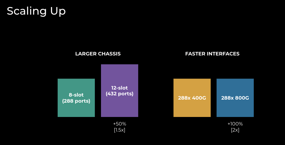 Figure 4: EBB techniques to scale up
In contrast to the dependency on vendors/industry in scaling up, scaling out (illustrated in Figure 5) is more under our control and has historically taken two flavors in EBB:
- Adding more Backbone planes. Going from four to eight planes results in doubling capacity globally; however, this technique has the following considerations:
- Implementation is quite disruptive and requires a lot of planning, specifically when it comes to fiber restriping (this needs to be coordinated in many locations simultaneously)
- Higher power and space requirements globally, but power density per rack remains the same
- Routing support for planes with uneven capacity can be complex
- Additional capacity on interconnects might be needed for compatibility with the final Backbone design
- Doesn’t require introducing new technology
- We can add multiple devices per plane. This technique is more sophisticated and allows us to scale capacity only in a chosen location. Considerations include:
- Implementation is quite disruptive for the target site and requires a moderate amount of planning to execute
- Higher power and space requirements in the target location, but power density per rack remains the same
- Interconnect with other layers might be more challenging: full mesh needs to be extended to Nx devices
- Introduces new failure modes: Device failure can impact some but not all of the of the Backbone in that plane/site
- Network operations can become more complex due to new failure modes and the handling of sets of devices (software upgrades, maintenance, etc.)
- Doesn’t require introducing new technology
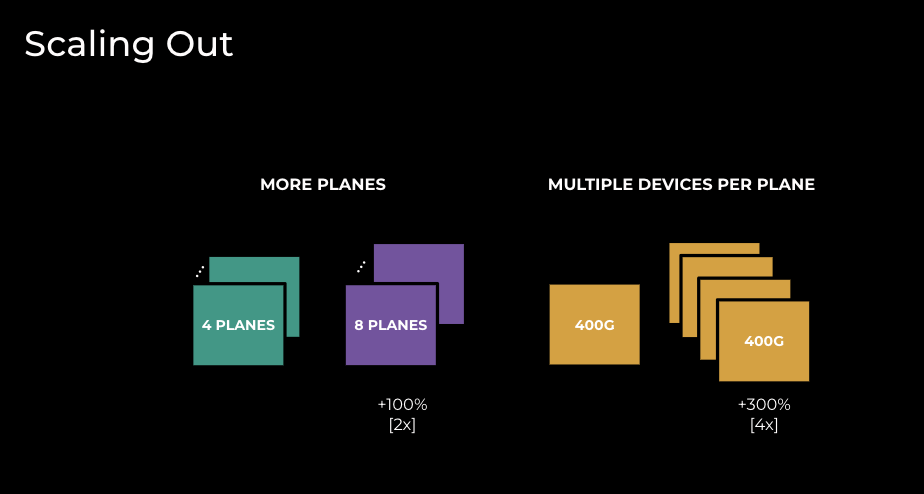 Figure 5: EBB techniques to scale out
Scaling up and scaling out are not mutually exclusive, and in our 10X Backbone journey we have used them both.
IP and Optical Integration
The third technique to scale to 10X Backbone is IP and optical integration. By leveraging ZR technology, we are changing the power footprint per terabit in the network.
Prior to ZR:
- We had many transponders per router. Each of the transponders consumed up to 2kW for 4.8-6.4Tb of capacity.
- There was a clear demarcation between IP and optical layers. This permitted work to occur at either layer with simple coordination.
With ZR:
- We no longer need transponders; this functionality is now in the plugs in the router. By removing transponders, we recover large amounts of space and power.
- Each of the plugs consumes 10-15W of incremental power.
- As a result of ZR plugs being installed in the routers, the split between IP and optical functions is not as clear as before.
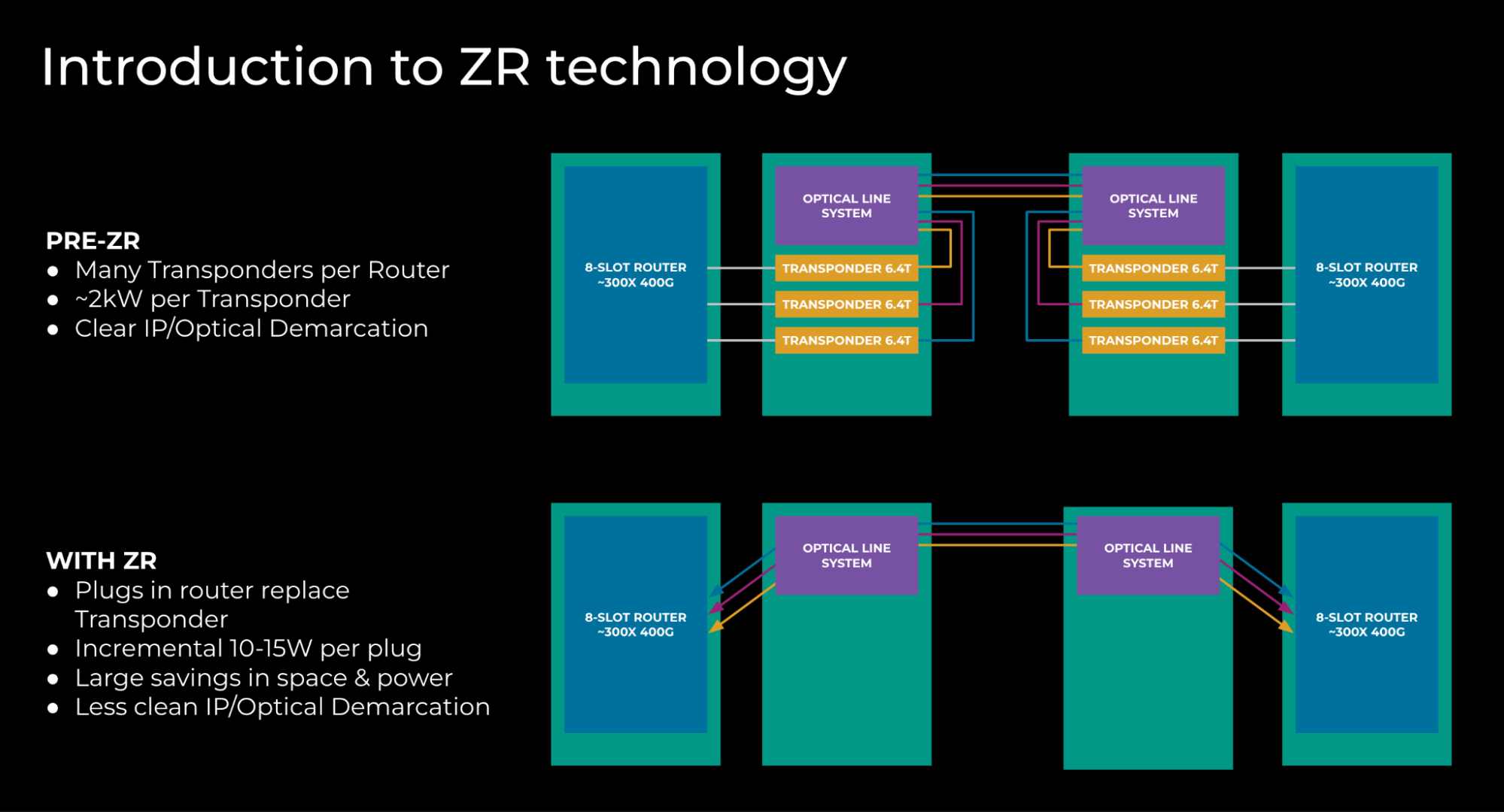 Figure 6: Network topology before and after ZR introduction
In summary, the use of ZR transceivers increases the power consumption in the router, which is offset by the considerable power savings from removing standalone transponders. In aggregate, we use 80 to 90% less power.
Using ZR technology has introduced important high-level changes:
- Cost and power efficiency:
- The same Backbone capacity can be deployed in a smaller S&P envelope
- Rack allocation between optical and IP devices goes from 90/10 (prior to ZR) to 60/40 (with ZR)
- Prior to ZR, we could land 1x fiber pairs/rack; with ZR, since we don’t use standalone transponders, we can land 4x fiber pairs/rack
- Simplifies network deployments; installing a set of pluggables instead of standalone transponders makes network deployments easier and more predictable
- Uses fewer active devices and therefore simplifies network operations
- Enables interoperability and vendor diversity
- Optical channel terminates in IP devices, and the demarcation of optical and IP is more complex than in non-ZR scenarios
- Telemetry and collections on the state of the optical channel is bound to IP devices, causing additional CPU consumption
By leveraging DC metro architecture, IP platform scaling, and IP/Optical integration, we transformed EBB from the experimental network of 2016 to a large-scale Backbone that supports all DC<>DC traffic at Meta.
AI Backbone
Over the last 18 months, we’ve seen an increasing interest in growing the megawatts footprint in support of building larger GPU clusters. The requirements have grown beyond what can fit in an existing data center campus, even considering undeveloped land or land adjacent to existing locations. Right now cluster performance is impacted by latency between endpoints, so we began to search for suitable expansion locations within bounded geographical proximity, expanding outwards until we achieve the target scale for a region.
As we identify sites of interest, we work with our fiber-sourcing team to determine the timing and feasibility to connect to existing locations at a very high scale as well as the most appropriate technology to utilize. In most cases, construction work is needed to place additional fiber in the ground, due to the significant quantities required.
We came up with three solutions based on the necessary reach:
- FR plugs: A solution that addresses buildings in the 3-kilometer range. (Note: We make some different assumptions about loss/connector count to permit this distance versus the standard specification, which states 2 kilometers.)
- LR plugs: Increasing the distance to a 10-kilometer range by using longer reach optics.
- ZR plugs + Optical DWDM (dense wavelength division multiplexing) technology: To go beyond 10-kilometer range, we need active optical components to multiplex and amplify the signals to get the desired reach. Multiplexing reduces the fiber count by a factor of 64 versus FR/LR.
For longer reach connectivity, a more complex solution is required. We use a relatively tried-and-tested design incorporating optical-protection switching, albeit using the latest generation C+L-Band 800G ZR technology.
Today’s requirements are at the lower end of the distance capabilities, and the initial deployments do not require any of the intermediate amplification sites that come into play when you go beyond 150 kilometers. This is fortunate, as these sites would be quite large given the amount of fiber pairs to be amplified (meaning additional lead times for construction, planning permits,etc.).
Protection switching introduces some additional operational challenges to how we run the network, as we require external tooling/monitoring to determine if the underlying connectivity for an IP circuit is in a protected or unprotected state. The primary reason to use them is to reduce the number of ports that we consume on the IP platforms, versus providing protection at the IP layer with additional capacity.
With this design, each fiber pair can carry 64x 800G (51.2T). To achieve the overall capacity needed between a given site-pair, we just scale this horizontally.
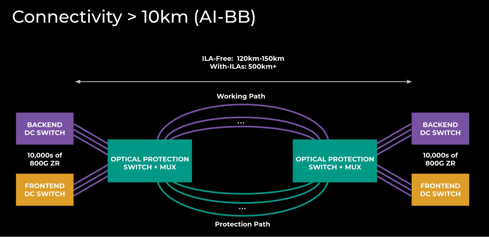
Figure 7: AI Backbone topology
The above diagram underscores the scale of these interconnects. Right now, a single AI Backbone site-pair is twice the size of the global backbone that we’ve been building for the last 10 years.
This presents many interesting challenges in how we deploy and provision this capacity. We’ll be putting a lot of time and effort into streamlining the sheer volume of this equipment and these connections as we complete the physical build-out of the fiber.
What We Learned and What the Future Holds
Scaling EBB has been a wild journey over the last eight or nine years, and it is a story of unexpected acceleration, where our scalability plans had to be accelerated, from 2028 to 2024.
These are our key learnings:
- 10x Backbone is possible because of the innovation in scaling up and scaling out.
- Pre-building scalable metro designs enables a faster response to network growth.
- IP/optical integration reduces the number of active devices, space and power footprint, and allows further scaling.
- Re-using 10X Backbone technology enables the build of AI Backbone.
Meta is planning to build city-size DCs, and our Backbone has to evolve and scale.
- We see leaf-and-spine architecture as the next step to scale out our platforms. This architecture provides the needed scale with fewer disruptive scaling steps.
- We will execute on the initial plan for AI Backbone, iterate as we go to more sites, and mature our operations. Throughout this process, we’ll come to understand AI intricacies as they develop through our optical network.
The post 10X Backbone: How Meta Is Scaling Backbone Connectivity for AI appeared first on Engineering at Meta.
This post first appeared on Read More